Use Case Diagram
Use cases were Ivar Jacobson's contribution to the UML notation. Although they are in most cases presented in a textual form, there is a special diagram in UML called Use Case Diagram (UCD), which is used to present their structure and associations with actors. In this article I will try to present you all necessary information to use UCD effectively.
Introduction
Use cases were Ivar Jacobson's contribution to the UML notation [1]. Although they are in most cases presented in a textual form, there is a special diagram in UML - Use Case Diagram (UCD), which is used to present their structure and associations with actors.
Use case diagram helps you visualize a set of use cases and provides basic information about use case model without a need of reading each of use cases. It is useful especially in early phases of requirements elicitation, when your model is still evolving and you have to introduce lots of changes to it (it is easier to "refactor" model on diagram than a textual use case.) Later on, as you will have more and more use cases refined to a textual form, such diagram can help your customer and other people involved, in understanding the scope of the system.
At this point you should consider reading an article "Introduction to Use Cases" in order to get a feeling what use cases really are.
System Boundaries and Packages
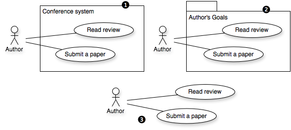
Use cases on Use case diagrams are in most cases presented within some boundaries. As presented in Figure 1 we have typically 3 possible situations:
- System boundaries - a scope of the system is presented as a rectangle with the name of the system in the upper part. Use cases which are placed inside the rectangle are handled by that system (are within the boundaries of that system). Actors are placed outside the boundaries.
- Packages - use cases are often grouped within packages (or functional modules.) In some cases you are interested in presenting only use cases which belong to a certain package, or dependencies of use cases between packages.
- No boundaries on diagram - in some cases you may like to present only a fragment (or a single aspect) of use case model, without presenting system boundaries. For instance you may like to present all use cases of a given actor, or all use cases which depend on a certain use case etc.
Fig. 1. Different boundaries in UCD: 1) System boundaries, 2) Package, 3) No boundaries
Actors
Actor represents a kind of entity which cooperates with the system under development (or other actors) in order to obtain a certain goal. Actor should be perceived as a role in the system.
In UML actors are represented by stick figures, with the name of an actor under the figure (see Figure 2.)
Fig. 2. An example of Actors in Use Case Diagram
Actors Generalization/Specialization
There is a relation available for actors, which is generalization/specialization. It works in the same way as in case of other UML elements. You express this relation by creating directed arc from the actor being specialization to the "more general" one (arc is finished with triangle). Example of this relation between actor Reviewer and Senior Reviewer is presented in Figure 3 (Senior Reviewer is a special case of a Reviewer.)
Fig. 3. An example of generalization/specialization relation between actors
It is important to not over-use this relation, which I often observe when people try to express permissions in the system through actors.
For example imagine you have an e-shop system, with two actors Customer and Administrator. You could be tempted to introduce generalization between Customer and Administrator, thinking "OK...Administrator can also buy things in the shop so it should be a specialization of Customer". Remember actor represents role, so the same person can act as different actors in different use cases (we will focus on this in the next section.) Use generalization only if there is a semantic reason for that, when one actor truly is a special case of a another one.
Actors and Real Users on Use Case Diagram <<acts as>>
When names of actors are the same as names of positions in organization it is difficult to explain that certain person in organization can play as different actors within different use cases.
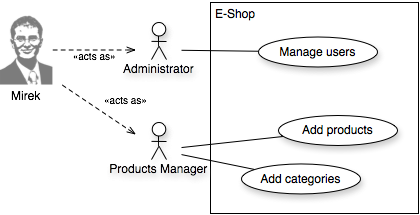
For example in the e-shop someone has to be responsible for adding new products. You have agreed with your customer that there will be a role Administrator, who will perform typical maintanance of the system (e.g. managing user accounts etc.) - and your customer has someone for that position in the company - lets call him John. You get to the point when you have to decide whose responsibility is adding new products. Your customer says "John will do this, so it is Administrator's task". You could say "OK", but you asked "will it always be John's task?". After a while your customer admitted that when the shop will grow, a new workers will be hired to manage products. So instead of assigning this task to Administrator (John in mind), you should rather introduce a new actor Products Manager, who will be responsible for managing products.
Why am I talking about this? Because if you introduce such "artificial" actors to improve your model, your customer can have problems in uderstanding how those roles relate to positions in organization and people. To solve this problem you can enhance your UCD with <<acts as>> relations [2]. You can introduce real people working in the organization (or positions in the organization) who will perform certain roles (act as certain actors.) You can see an example of this relation in Figure 4. We can see that Mirek will fulfil Administrator and Products Manager roles.
Fig. 4. Example of using <<acts as>> to present people or positions in organization playing as actors
Use Cases
Each use case is presented on UCD as an elipse with its name placed inside.
Associations Between Actors and Use Cases
Actors, which are placed on UCD outside the system boundaries, are associated with use cases in which they participate and which represent meaningful goals for them.
Typically actors and use cases are connected with non-directed arcs, which are presented in Figure 5 (marked with label 1). This kind of connection tells us only that a certain actor participates in a given use case. If there are more than one actors connected with the same use case, that means that they are both participating in that use case. You can also provide some additional information, by changing non-directed arcs to directed ones [3]. In that case if an arc is directed from an actor to a use case (see Figure 5, label 2) it means that the actor is a primary actor of this use case, if it is directed from the use case to the actor that means that actor is a secondary actor (see Figure 5, label 3.)
Figure 5 presents also multiplicity of associations. According to [2] multiplicity states "how many instances of the use case one instance of the actor (one user playing the role defined by the actor) may simultaneously communicate with, and vice versa." In case of diagram presented in Figure 5, we can say that one Participant will communicate with one instance of "Register to conference" at a time, and each instance of "Register to conference" will communicate with one Participant at a time. A single Participant can also communicate with a one instance of "Book hotel" at a time, and each instance of "Book hotel" will communicate with one Participant and Hotel Reserver (typically a hotel booking system.) However, a single instance of Hotel Reserver can be contacted by many instances of "Book hotel" use case.
Fig. 5. Different connections between Actors and Use Cases: 1) actors participates in a use case (the most general case), 2) Primary actor of use case, 3) Secondary actor of use case
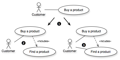
Do I have to associate all of my use cases with actors? No. You have to connect actors with use cases which are "important" for them. In some cases you will do some "refactoring" of your model by extracting some reusable use cases to simplify the model. Such use cases will not have to be associated with actors if they are not representing standalone goals for them. An example of such situation is presented in Figure 6.
Fig. 6. Alternative evolutions of the same use case model and associations between the actors and use cases: 1) New use case "Find a product" was extracted from the "Buy a product" one, 2) Analyst decided that finding a product is not directly important for Customer (Customer will not look for products just to find them...), 3) Analyst decided that finding a product could be a goal itself for the Customer (Customer may be interested in just finding a product)
Relations Between Use Cases
There are three types of relations between use cases: inclusion, extension, and generalization/specialization. Each of this relations can be presented on UCD.
Inclusion Relation <<include>>
The inclusion relation is presented on a diagram as a dashed arc with an arrow and label <<include>> (or <<includes>>, and sometimes <<uses>>.) If use case A includes use case B, you will have to create an arc from use case A to use case B. This means that in order to complete goal of use case A, actor will have to complete goal of use case B (this doesn't mean that actor will always have to complete a use case B; use case B can be included in main scenario or any of the alternative scenarios - but if actor follows the scenario with inclussion, execution of use case B will be obligatory!) An example of this relation is presented in Figure 7. In order to review a paper one has to read this paper.
Fig. 7. Example of <<include>> relation between use cases
Extension Relation <<extend>>
The extension relation is presented on a diagram as a dashed arc with an arrow and label <<extend>> (or <<extends>>.) If use case B extends use case A, you will have to create arc from use case B to use case A. This means that in some point of execution of use case A, actor may like to complete goal of use case B. An example of this relation is presented in Figure 8. When PC Chair is assigning reviewers to papers, he/she may like to read a certain paper to make a better choice (however reviewers can be also assigned based on title or abstract, without a need of reading the paper.)
Fig. 8. Example of <<extend>> relation between use cases
Generalization/Specialization Relation
This relation is easy to handle on diagrams but not so easy when it comes to textual description of use case. It is represented by an arc with triangle. If use case A is a generalization of use case B, you will have to draw an arc from B to A. It works also in the opposite way - you can also say that use case B is a specialization of use case A (still you will have to draw an arc from B to A.) This would mean that use case B "inherits" all scenarios from A, which can be changed or extended. An example of this relations is presented in Figure 9. There is a simple way of assigning reviewers to papers by PC Chair (arbitrary assignment.) There is also additional (specialized) way of doing the same by letting Reviewers bid for the papers they would like to review.
Fig. 9. Example of generalization/specialization relation between use cases
Some Practical Hints & Pitfalls
- "one picture tells 1000 words" ... one diagram with 1000 use cases tells nothing ... - avoid creating diagrams with overall view of the system if there are more than 10-15 use cases. Remember that a single UCD doesn't have to present all use cases in your model. You can present single packages, most important use cases, some important parts of your model etc. UCD goal is to help understand the model, but if you put like 30 use cases with 30 relations on your diagram, it will be hard to read.
- start from main goals not from minor ones - the general rule is breadth before depth [4]. Start from identifying main goals, then you can do some "refactoring" to extract some reusable use cases, to be used as <<include>> relations. It may sound obvious, but from my experience when people are asked to create diagram for the e-shop like system (for the first time), they start from goals like adding and removing products from/to the basket, and not from the most general one - buy a product! This leads to very complicated models at a level of abstraction close to steps of a single use case (in most cases there is no "buy a product" use case in their final model.)
- use case diagrams don't present scenarios - UCD doesn't present the sequence of use cases which has to be performed. This is the role of use-case scenarios, which are placed in use case description (for example in textual form). That's why if we talk about relations like <<include>>, we say that in order to obtain a goal of use case A (which e.g. includes use cases B and C) actor may have to obtain goals of use cases B and/or C, and not that actor first will have to obtain a goal of use case B and then C.
- keep use case description in mind while creating diagrams - UCD diagrams are great tool for elicitation of use cases. It is easy to discuss use cases if you can visualize them on diagram and on-demand change relations etc. However it is always a good idea to keep in mind how textual representation of those use cases may look like in the future. Why? I observed that very often people tend to go deeper and deeper into sub-goals of use case, which finally leads them to have use cases which are actually single steps of use case which includes them. For example if you have a "Review a paper" use case, you may start to extract (and include) use cases like "Choose a paper", "Read a paper", "Add a text of review to the paper", "Rate a paper" etc. From these goals maybe "Read a paper" is a good option for a extraction as a separate use case, because it may be re-used by other use cases, the rest of them are single steps of "Review a paper" use case.
- pre-conditions and use cases - sometimes people perceive inclusion and extension relations as pre-conditions. It is not a good idea to assume that.
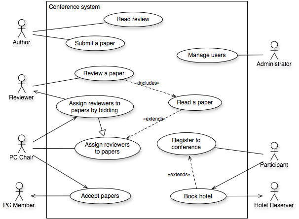
- don't use actors to represent permissions - you can be trapped by trying to express perimissions through the actors. I will repeat it over and over again, but actors represents roles, and single user of the system can play different roles. Often made mistake is to try creating hierarchy of actors to express permissions. How it looks like? For example if we consider system presented in Figure 10, you may think "Author can submit a paper, hmm... Administrator also can, and PC Member too..., OK, so they all should be specializations of Author...". It doesn't work that way. Sooner or later you will have a problem of overlapping "permissions". So you better use other approach to express permission control (I will try to write a separate article about that somwhere in the future).
- many actors in the same use case - if there are more than one actor associated with the same use case, this means that they are all cooperating in the scenarios of this use case; and not that each of them may like to execute that use case! This problem also relates to permissions. You may think that Author and PC Member may like to read a paper so they should be both associated with the "Read a paper" use case. No! It would mean that they both are required to complete that use case - for instance PC Member holds a book and Author reads it ;) If you would like to express such a thing you can introduce an additional actor like "Paper Reader", and do one of two things: use generalization/specialization to show that both Author and Reviewer are Paper Readers or just leave it alone and in the description of the Paper Reader write "All people who are interested in reading a paper".
Example of Usage
Fig. 10. Example of complete use case diagram - Conference System
References
- OMG (2008). OMG Unified Modeling Language (OMG UML), Superstructure, V2.1.2 p.585-603.
- G. Övergaard and K. Palmkvist. Use cases: patterns and blueprints. Addison-Wesley, 2005.
- K. Wiegers. More about software requirements: Thorny issues and practical advice. Microsoft Press Redmond, WA, USA, 2005.
- A. Cockburn. Writing effective use cases. Addison-Wesley Boston, 2001.


 Previous:
Plone CMS - a set of products to build a site


Nice article