Use-Case Relations - Diagram and Text
In this blog entry, I would like to show you how the relations (include, and extend) between use cases are presented on use case diagrams and how to use them in textual representations of use cases.
Introduction
I think I have already written about the relations between use cases twice. Last time, in the entry about use case diagrams (UCD), I mentioned that it is good to keep in mind the textual representation of use cases while constructing relations between them on diagram. Here, I would like to show you how those relations between use cases are presented on diagrams (which you should already know from the previous entries), and how we use them in the textual representation.
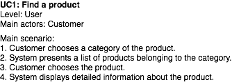
I will use a simple example (sorry if it is too simple) of the use case entitled "Find a product", with id UC1. The textual representation of this use case is presented in Figure 1. You can see that it has a basic main scenario: Customer chooses a category, System displays items in this category, Customer chooses the product, and voila!
Fig. 1. A basic textual representation of the use case "Find a product"
Inclusion Relation Between Use Cases
The inclusion relation between use cases tells you that in order to complete the goal of one use you have to complete also the goal of included one. OK, lets get back to the example and see how it works. The main scenario in UC1 presents you how to find a product by "browsing" through categories. There might be also alternative way to accomplish that goal by searching for the product (i.e. providing search criteria and so on.) In Figure 2, you can see that we have a special use case entitled "Search for product", which describes a scenario we were looking for. Lets include that use case to the use case UC1 "Find a product".
Fig. 2. "Find a product" includes the "Search for product" use case on UCD
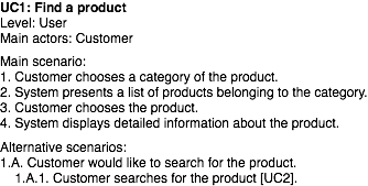
This is a good example of the inclusion relation, however a specifc one. Why? Because the inclusion is not done from the main scenario (which is I think the most common case), but from the alternative one. You can see in Figure 3, that the alternative scenario was added to the UC1. I don't know about any standardized way of presenting invocation of one use case from another one. We are doing this by putting the id of ivoked use case in the square brackets in the step of use case where it is invoked (see Figure 3, and step 1.A.1.)
Fig. 3. Textual representation of "Find a product", with inclusion of "Search for product"
Easy, isn't it? So where are typical problems here? I think the main problem is when you are modeling with the use of UCD, and you are treating steps as included use cases. If you think how your use cases will look like in the textual representation, it will be easier for you to find a proper abstraction level for your use case diagrams.
Extension Relation Between Use Cases
If we think about the extension relation and textual representation of use cases, there are at least two approaches to model this relation.
Lets start from the explicit extension (this is not the offical name.) Imagine, that in our system Customer can add products to the list of favorites ones. There is even a sepearte use case describing that, called "Add products to favorites". The starting point for that use case is when a list of products is displayed. Hmm, in our use case "Find a product" in step 2. a list of products is displayed. So we can decide that the UC3 "Add products to favorites" extends the UC1, as presented in Figure 4.
Fig. 4. "Add products to favorites" use case extends the "Find a product" one on UCD
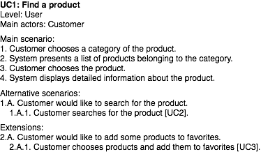
How to present this relation in the textual representation? If we use the "explicit" approach, which means that UC1 knows that it can be extended by the use case UC3 after the step 2, we can use the approach presented in Figure 5. As you can see, we have extension attached to step 2 with the invocation of UC3.
Fig. 5. Textual representation of the extension relation (UC1 explicitly knows that it can be extended by the UC3)
We can also do the same by using extension points mechanism. It works in the opposite way. If you use it, a use case which is extended exposes some places (which are called extension points) where other use cases can add their scenarios. In this case extended use case is not aware of use cases which are extending its scenarios.
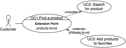
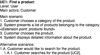
We can also use this approach to our example. In Figure 6, we defined the extension point called "products found" within the use case "Find a product".
Fig. 6. "Add products to favorites" use case extends the "Find a product" one through the extension point
We are not able to see where exactly this extension point is placed in the use case senarios on the use case diagram. However, if the textual form of use case is considered we can define exact places in scenarios for the extension point (see Figure 7.)
Fig. 7. Definition of the extension point in the use case "Find a product"
Conclusions
Use case diagrams are living in symbiosis with the textual representations of use cases. If you want to master use-case modeling, you will have to learn how they relate to each other in order to be able to use both of them effectively.



 Poprzedni: Review of book: Function Point Analysis: Measurement Practices for Successful Software Projects


